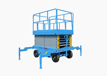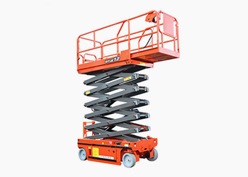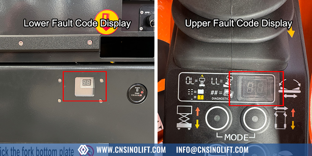
SINO LIFT GTJZ series self-propelled scissor lifts are used in factories, warehouses, construction sites, and maintenance projects. When the control system detects an electrical, hydraulic, battery, or safety issue, it displays a fault code and may stop part or all machine functions.
This guide is based on SINO LIFT GTJZ series electric self-propelled scissor lifts and SINO LIFT controller documentation. Fault code display text and available codes can vary by controller version, drive type, battery type, and machine configuration. Always cross-check the code table in the manual supplied with your machine.
Fault codes are also commonly referred to as error codes or alarm codes. This guide uses “fault codes” for consistency.
The purpose of this page is to help operators and technicians record the code, understand the machine status, check likely causes, and decide whether the issue can be solved on site or should be sent to SINO LIFT technical support.
Before any inspection, follow these basic safety steps:
Electrical measurements, controller checks, and component replacement should be performed by a qualified technician familiar with the machine. Operators should limit themselves to visual checks and basic safety checks described in the operator’s manual.
Safety circuits are not obstacles. They are the reason the machine stops before a small fault becomes an accident. For a deeper look at how SINO LIFT designs scissor lift safety features, including overload protection, tilt detection, and emergency systems, see the dedicated safety guide.
When a fault code appears, do not reset the machine repeatedly without recording information. First, write down:
Take a photo of the controller display. This helps SINO LIFT support identify the controller version and fault history.
A reset may clear a temporary alarm, but it does not correct the underlying fault. If the same code returns, stop repeatedly resetting the machine and identify the root cause.
After recording the code, shut down safely and inspect the machine visually. Many faults are caused by loose connectors, damaged wiring, low battery voltage, or a safety switch that is not triggered. Regular daily inspection can often catch these issues before they trigger a fault code.
Looking for a specific code? Use your browser’s Find function (Ctrl + F or Command + F) and enter the code number.
The following tables are based on SINO LIFT controller documentation for GTJZ electric self-propelled scissor lifts. Some codes apply only to electric drive models or ZAPI controller systems. Check your machine manual for exact code availability.
| Code | Display Description | Applies To | Machine Status | What to Check |
|---|---|---|---|---|
| 01 | System initialization error. On applicable controller versions, the PCU may display 10 for the same initialization condition. | Controller version dependent | Stop all actions. | Check power supply, connectors, and ECU. If the fault continues after basic checks, the ECU may need replacement. Contact SINO LIFT support. |
| 02 | System communication error. On some controller versions, the PCU may display 20 for the same communication condition. | Controller version dependent | Stop all actions. | Check communication wires and other wiring. If the problem remains, test or replace the PCU or ECU. Confirm controller type before diagnosis. |
| 03 | Invalid parameter setting error. | GTJZ electric models | Stop all actions. | Set the correct machine options for the controller. |
| 10 | System initialization error shown on PCU. This is the PCU display for the initialization condition that may appear as 01 on the ECU, depending on controller version. | PCU display | Stop all actions. | Same direction as code 01. Check PCU/ECU power, wiring, and communication. |
| 12 | Chassis up/down button activation error on startup. | Chassis control | Stop chassis operation. | Check the toggle switch wiring. Check whether the toggle switch is stuck. |
| 18 | Pothole protection error. | Pothole protection system | Stop lifting and travelling. | Check if the pothole protection is extended. Check the pothole protection limit switch and wiring. Check the lower stop limit switch and wiring. |
| 20 | System communication error shown on PCU. On some controller versions, this is the PCU display for the condition shown as 02 on the ECU. | PCU display / controller version dependent | Stop all actions. | Treat as a communication error. Check wiring, PCU, and ECU. Confirm controller version before diagnosis. |
| 31 | Pressure sensor error. | Pressure sensor / load sensing circuit. Terminology may vary by controller manual. | Stop all actions. | Check sensor wiring and the sensor itself. Confirm the correct pressure, load, or weight sensor option is selected according to the controller manual. Use the term shown in your controller documentation. |
| 32 | Angle sensor error. | Angle sensor system | Stop all actions. | Check sensor wiring and the sensor itself. Confirm the correct sensor option is selected. |
| Code | Display Description | Applies To | Machine Status | What to Check |
|---|---|---|---|---|
| 42 | Left steering button error on startup. | Joystick/PCU | Alarm only. | Make sure nothing is pressing the button on the joystick. If normal, consider replacing the joystick or PCU. |
| 43 | Right steering button error on startup. | Joystick/PCU | Alarm only. | Make sure nothing is pressing the button on the joystick. If normal, consider replacing the joystick or PCU. |
| 46 | Joystick operation error on startup. | Joystick/PCU | Stop platform operation. | Make sure nothing is pressing the enable switch. Check zero position parameters. If normal, consider replacing the joystick or PCU. |
| 47 | Joystick not at zero position on startup. | Joystick/PCU | Alarm only. | Ensure the joystick is at zero position, vertical. Check zero position parameter settings in the scissor program. If normal, consider replacing the joystick or PCU. |
| Code | Display Description | Applies To | Machine Status | What to Check |
|---|---|---|---|---|
| 52 | Forward coil error. | Coil-controlled functions | Stop lifting and travelling. | Check coil connections. Confirm correct wiring. If normal, check whether the coil is short-circuited or open-circuited. |
| 53 | Reverse coil error. | Coil-controlled functions | Stop lifting and travelling. | Check coil connections. Confirm correct wiring. If normal, check for short or open circuit. |
| 54 | Lift up coil error. | Coil-controlled functions | Stop lifting and travelling. | Check coil connections. Confirm correct wiring. If normal, check for short or open circuit. |
| 55 | Lift down coil error. | Coil-controlled functions | Stop lifting and travelling. | Check coil connections. Confirm correct wiring. If normal, check for short or open circuit. |
| 56 | Right steering coil error. | Coil-controlled functions | Stop lifting and travelling. | Check coil connections. Confirm correct wiring. If normal, check for short or open circuit. |
| 57 | Left steering coil error. | Coil-controlled functions | Stop lifting and travelling. | Check coil connections. Confirm correct wiring. If normal, check for short or open circuit. |
| 58 | Brake coil error. For hydraulic drive models, check machine code. | Electric drive / coil-controlled functions | Stop lifting and travelling. | Check coil connections. Confirm correct wiring. If normal, check for short or open circuit. |
| 59 | Parallel valve coil error. | Coil-controlled functions | Stop lifting and travelling. | Check coil connections. Confirm correct wiring. If normal, check for short or open circuit. |
Codes above 60, except 68, 80, 90, and 99, apply only to electric drive models. Codes 80, 90, and 99 represent load weight percentage. They are explained in the Load and Safety Protection Codes section.
| Code | Display Description | Applies To | Machine Status | What to Check |
|---|---|---|---|---|
| 61 | Motor controller current sensor error. | Electric drive models | Determined by motor controller. | The travel or lift motor may be overheated. Let the machine cool down. Restart or reset the motor controller. Check wiring. If wiring is normal, replace the motor controller. |
| 62 | Motor controller hardware damage error. | Electric drive models | Determined by motor controller. | Restart the machine. If the fault remains, check for noise sources. If the problem continues, replace the motor controller. |
| 63 | Motor controller motor output error. | Electric drive models | Determined by motor controller. | Check wiring, then restart. If unresolved, replace the motor controller. |
| 64 | Motor controller SRO error. | Electric drive models | Determined by motor controller. | Use a handheld programmer to check the motor enable delay parameter. It may be set too short. Do not change the parameter unless the correct value is confirmed in the controller or machine manual. |
| 65 | Motor controller throttle valve error. | Electric drive models / controller-specific | Determined by motor controller. | Check wiring. Confirm the correct throttle valve type or throttle input setting is selected in the motor controller. If your controller manual uses a different term, follow the controller manual. |
| 66 | Motor controller emergency reverse error. | Electric drive models | Determined by motor controller. | Have a qualified technician verify the emergency reverse check parameter according to the controller manual. Do not change safety-related parameters without confirming the correct setting for the machine. |
| 67 | Motor controller HPD error. | Electric drive models | Determined by motor controller. | Use a handheld programmer to check the motor enable delay parameter. It may be too short. Do not change the parameter unless the correct value is confirmed in the controller or machine manual. |
| 68 | Low voltage alarm. | GTJZ electric models | Stop all actions. | Check battery voltage and charge if necessary. Check battery and switch connections. Tighten or clean them. Check supply voltage to ECU and PCU. |
| 69 | High zero current error. ZAPI system only. | ZAPI controller | Stop all actions. | Large current detected inside the motor. If the alarm appears while the motor is operating normally, check the motor and controller status according to the machine manual. Do not ignore a persistent alarm. |
| 70 | Steering output out of set range. ZAPI system only. | ZAPI controller | Stop all actions. | The ZAPI controller may need recalibration. |
| 71 | Main motor contactor error. | Electric drive models | Unable to travel and lift. | Check main contactor wiring. Replace the contactor if necessary. |
| 72 | Motor controller over voltage error. | Electric drive models | Determined by motor controller. | Check battery voltage. Inspect the battery interior if needed. |
| 73 | Motor controller error. | Electric drive models | Determined by motor controller. | Check circuit wiring or replace the motor driver, ZAPI motor controller. |
| 74 | Motor controller motor fault. | Electric drive models | Determined by motor controller. | Check circuit wiring or replace the motor driver, ZAPI motor controller. |
| 75 | Motor controller pump motor error. | Electric drive models | Determined by motor controller. | Check circuit wiring or replace the motor driver, ZAPI motor controller. |
| 76 | Motor controller left drive motor error. | Electric drive models | Determined by motor controller. | Check circuit wiring or replace the motor driver, ZAPI motor controller. |
| 77 | Motor controller right drive motor error. | Electric drive models | Determined by motor controller. | Check circuit wiring or replace the motor driver, ZAPI motor controller. |
| 78 | Pump motor short circuit error. | Electric drive models | Determined by motor controller. | Check wiring or replace the motor driver, ZAPI motor controller. |
| 79 | Left drive motor short circuit error. | Electric drive models | Determined by motor controller. | Check motor connection and ensure the motor works normally. |
| 81 | Right drive motor short circuit error. | Electric drive models | Determined by motor controller. | Check the motor connection wires. Check whether the motor is short-circuited. |
| 82 | Right brake coil error. | Electric drive models | Stop lifting and travelling. | Check coil terminals and ensure they are tightened. If tightened, check whether the coil is short-circuited or open-circuited. |
| 83 | Left brake coil error. | Electric drive models | Stop lifting and travelling. | Check coil terminals and ensure they are tightened. If tightened, check whether the coil is short-circuited or open-circuited. |
Codes 80, 90, and 99 indicate the approximate load percentage rather than a component fault. OL and LL are safety protection codes.
| Code | Display Description | Applies To | Machine Status | What to Check |
|---|---|---|---|---|
| 80 | Over 80% load alarm. | Load monitoring | Alarm only. | The platform is close to maximum load capacity. Do not add more load. |
| 90 | Over 90% load alarm. | Load monitoring | Alarm only. | The platform is close to maximum load capacity. Do not add more load. |
| 99 | Over 99% load alarm. | Load monitoring | Alarm only. | The platform has reached its load limit. Do not add any more load. |
| OL | Platform overload error. | Overload protection | Stop all actions. | Remove the excess load immediately. |
| LL | Machine tilt exceeds safety limit. | Tilt protection | Stop lifting and travelling. | If the machine is tilted, level it. If the machine is level, check the wiring of the tilt sensor and the sensor itself. |
Some controller versions may display E-codes or text alarms instead of the numeric codes listed above. The troubleshooting approach below can help with common symptoms, but the exact meaning of an E-code depends on the controller version and machine configuration. Do not assume that E01 corresponds to code 01 unless the machine manual confirms it.
Check both platform and chassis emergency stop buttons. Rotate to reset if pressed. Power off and inspect wire terminals for looseness, oxidation, or breakage. A qualified technician should test switch continuity with a multimeter. Replace the switch if there is no continuity.
Remove extra materials and reduce platform weight first. Restart and check if the alarm clears. If the alarm remains with a light load, inspect the load sensor installation and cables. Recalibrate or replace the sensor if needed. Do not disable overload protection.
Shut down and charge the batteries fully. Check battery terminals for corrosion and tighten loose connectors. Test individual battery cell voltage. Replace aged batteries if voltage drops quickly under load. Inspect charger output and charging cable.
Check hydraulic oil level and oil quality according to the maintenance manual. Top up with the recommended hydraulic oil if low. Check hoses, fittings, and cylinders for leaks. Replace a clogged hydraulic filter according to the maintenance manual. Inspect pressure sensor wiring and signal. If pressure cannot build up, inspect the hydraulic pump and relief valve according to the maintenance manual. For a focused guide on oil selection, leak detection, and common hydraulic problems, see the hydraulic system maintenance guide.
Power off and clean dirt around the limit switch. Adjust the switch mounting position to ensure normal trigger. A qualified technician should test switch continuity with a multimeter. Replace a defective switch. Check the wire harness for abrasion damage.
Let the machine cool down if an overheating alarm is triggered. Check motor wiring terminals for burning or looseness. Inspect the motor speed feedback sensor. Check the controller error log. Do not force travel when a drive motor fault is active.
Move the scissor lift to flat, level ground and restart. Check the mounting bracket of the tilt sensor. Test the sensor signal. Recalibrate or replace the sensor when needed. The lift will disable lifting under tilt protection to prevent rollover.
Use this process every time a fault code appears.
Sometimes the machine malfunctions without showing a fault code.
Regular preventive maintenance reduces fault alarms and extends the service life of your SINO LIFT self-propelled scissor lift.
Contact the service team in these cases:
Before contacting SINO LIFT, prepare the following information:
This information helps the support team identify the issue faster and reduces unnecessary back-and-forth. If you are weighing repair versus replacement, the scissor lift repair cost guide outlines typical cost ranges for common failures.
Do not continue normal operation when the fault code locks lifting or travelling. Safety-related codes such as tilt, overload, and pothole protection are designed to stop the machine. Find the cause and correct it before resetting the machine.
A returning fault code usually means the root cause is still present. Common causes include oxidized terminals, a weak battery cell, a loose sensor, or damaged wiring. Repeated resetting does not solve the underlying problem.
Check the controller plug and power supply voltage first. If power is normal and the display still fails, the controller board may need replacement. Contact SINO LIFT support with the machine model and photos.
The operator’s manual and maintenance manual supplied with the machine include the fault code table, usually in the troubleshooting section. If the manual is lost, contact your dealer or SINO LIFT support with the machine serial number.
Many self-propelled scissor lifts lock travel when the platform is raised. This is a normal safety function. Check the manual for your model’s travel-lock conditions.
For lead-acid batteries, capacity can drop significantly below 0°C. This does not always mean the battery is damaged. Charge the battery in a suitable environment and check voltage under load.
Record the exact fault code, machine model, serial number, machine hours, working environment, and what the machine was doing when the alarm appeared. Take photos of the controller display and any damaged parts. Also note the troubleshooting steps you have already tried.
No. Fault code availability and display text can vary by controller version, drive type, battery type, and machine configuration. Always check the manual for your specific machine before replacing parts or changing settings.
SINO LIFT self-propelled scissor lift fault codes are part of the machine’s safety communication system. Record the code, understand the machine status, check the simple causes first, and do not bypass safety circuits.
Most common alarms can be narrowed down with basic checks: battery voltage, emergency stop, wiring connections, sensors, hydraulic oil level, and mechanical blockage. For motor controller, hydraulic, or safety-related faults, professional support is the safer path.
If you need spare parts, technical support, or service advice for your SINO LIFT scissor lift, contact our team. Please include the machine model, serial number, fault code, and photos so we can help you faster. For help evaluating a new unit before purchase, the scissor lift selection guide covers types, parameters, and selection criteria. The scissor lift price guide provides typical cost ranges by type and height.
HENAN SINO LIFT manufactures Scissor Lifts, Mast Lifts, Boom Lifts, Cargo Lifts, Loading Ramps, Wheelchair Lifts, and Warehouse Handling Equipment.
For spare parts, technical support, or product information, contact our team with your machine model and requirements.
Email: info@cnsinolift.com
Website: www.cnsinolift.com